Support our educational content for free when you buy through links on our site. Learn more
🤖 How Battle-Ready Robots Are Designed (2026)

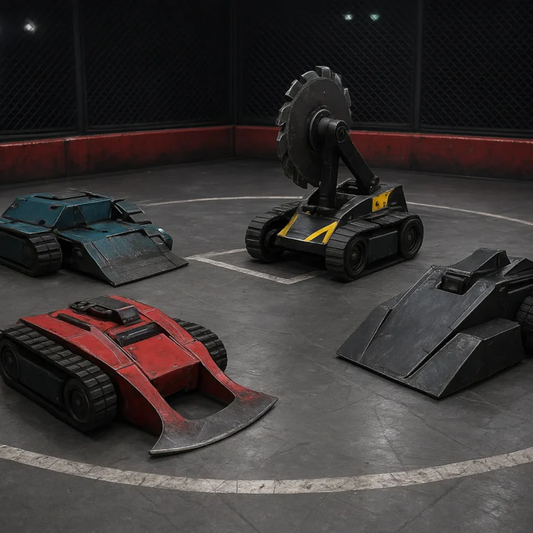
Robot designers create battle-ready robots by balancing rules, mobility, weapon performance, armor, electronics, safety, and rapid repairability rather than chasing maximum power in one subsystem. The winning recommendation is simple: design the complete fighting system first, then optimize each part around reliability and the competition rulebook.
So, how do robot designers create battle-ready robots for competition? They translate event rules into engineering requirements, choose a clear combat strategy, model the robot in CAD, calculate weight and energy, prototype the drivetrain and weapon, protect critical electronics, and test until predictable failure points are gone. Our guide to 🤖 Robot Wrestling Rules & Scoring Explained (2026) is the sensible starting gate.
We have seen teams spend weeks perfecting a weapon, only to discover that a loose battery connector ends the match before the first meaningful hit. In robot wrestling, the unglamorous details matter: a protected ESC, accessible fasteners, a secure battery, a reliable failsafe, and a driver who can still control the machine after it gets flipped.
A competition robot also needs a practical pit strategy. The best designs use modular armor, common fasteners, replaceable wheels, labeled wiring, and spare parts that let a team return to the arena quickly instead of performing emergency surgery with a tiny hex key.
The intriguing part is that the most destructive robot is not always the most dangerous opponent. A slightly less powerful machine that moves reliably, survives impacts, and gives its driver consistent control can outlast a spectacular design that overheats, sheds parts, or cannot recover from a bad hit.
Key Takeaways
- Start with the rules: Weight, dimensions, safety systems, batteries, radio controls, and weapon restrictions define the design envelope.
- Choose a combat strategy early: A vertical spinner, horizontal spinner, flipper, hammer, lifter, wedge, or control bot needs different geometry and engineering trade-offs.
- Prioritize mobility and reliability: A robot must approach, escape, turn, recover, and keep operating after impact.
- Use CAD and a live weight budget: Model clearances, fasteners, wiring, weapon motion, center of gravity, and repair access before fabrication.
- Protect critical systems: Secure batteries, shield ESCs and receivers, add strain relief, and manage shock, heat, dust, and debris.
- Design for rapid repairs: Modular armor and accessible components can matter as much as raw weapon energy during a tournament.
- Test progressively: Validate electronics, drivetrain, weapon, thermal performance, failsafes, and complete match simulations before competition.
- Train the driver: Precise control, matchup awareness, and risk management can beat a robot with greater theoretical power.
- Build in safety from the start: Weapon locks, main disconnects, visible power indicators, and radio failsafes are essential—not optional accessories.
Table of Contents
- ⚡ Quick Tips and Facts for Designing Battle-Ready Robots
- 🤖 What Makes a Robot Truly Battle-Ready?
- 🕰️ From Robot Wars to Modern Combat Robotics: How Competition Design Evolved
- 🏆 Choosing the Right Combat Robot Class, Weight Limit, and Competition Format
- BattleBots, Robot Wars, NHRL, and Other Major Competition Rules
- Antweight, Beetleweight, Hobbyweight, and Heavyweight Robots Explained
- How Arena Hazards, Match Length, and Judging Criteria Affect Design
- 🧠 The 15-Step Robot Design and Engineering Workflow
- 1. Translate Competition Rules into Engineering Requirements
- 2. Define a Winning Strategy and Robot Archetype
- 3. Select the Chassis Layout and Drive Configuration
- 4. Choose Between a Vertical Spinner, Horizontal Spinner, Flipper, Hammer, or Control Bot
- 5. Calculate Weight Distribution and Center of Gravity
- 6. Model the Robot in CAD Before Cutting Material
- 7. Design for Manufacturability, Assembly, and Rapid Repairs
- 8. Engineer the Drive System for Traction and Maneuverability
- 9. Size Motors, Gearboxes, Batteries, and Electronic Speed Controllers
- 10. Design the Weapon System for Energy, Reliability, and Control
- 11. Select Armor Materials and Build a Protective Shell
- 12. Protect Batteries, Wiring, Sensors, and Radio Electronics
- 13. Add Safety Interlocks, Power Isolation, and Fail-Safe Controls
- 14. Prototype, Test, Break, and Improve the Robot
- 15. Prepare Spares, Match Tactics, and a Competition Pit Strategy
- 🛠️ Combat Robot CAD and Digital Prototyping Techniques
- SOLIDWORKS, Fusion 360, and Other Mechanical Design Tools
- Parametric Modeling for Fast Armor and Weapon Revisions
- Motion Studies, Interference Checks, and Assembly Validation
- Finite Element Analysis for Chassis, Weapon, and Armor Stress
- Taming the Mesh: Cleaning 3D Scan Data for Accurate Robot Parts
- ⚙️ Mechanical Architecture: Chassis, Drive Trains, and Modular Construction
- Four-Wheel Drive, Two-Wheel Drive, and Six-Wheel Drive Compared
- Invertibility, Ground Clearance, and Getting Un-Stuck After a Flip
- Modular Chassis Design for Faster Repairs Between Matches
- Bearing Mounts, Shafts, Fasteners, and Tolerance Planning
- 🔋 Power Systems and Electronics for Combat Robots
- LiPo Batteries, Voltage Selection, Capacity, and Discharge Ratings
- Brushless and Brushed Motors for Drive and Weapon Systems
- Electronic Speed Controllers, Current Limits, and Thermal Management
- Radio Control Links, Receivers, Antennas, and Signal Reliability
- Wiring Layout, Connectors, Fuses, and Electromagnetic Interference
- 💥 Weapon Engineering: Turning Stored Energy into Controlled Chaos
- Vertical Spinner Design: Bite, Tip Speed, and Self-Righting
- Horizontal Spinner Design: Reach, Gyroscopic Effects, and Chassis Stability
- Drums, Beaters, Discs, and Full-Body Spinners Compared
- Flippers, Lifters, Hammers, and Grabers for Control-Based Combat
- Weapon Material Selection, Balancing, Shafts, and Impact Loads
- Weapon Brakes, Lockouts, Guards, and Safe Testing Procedures
- 🛡️ Armor and Impact Protection: Keeping the Robot Alive
- AR500 Steel, Aluminum, Titanium, UHMW-PE, and Polycarbonate
- Sacrificial Armor, Deflection Angles, and Replaceable Panels
- Top Armor, Side Armor, Wedges, Forks, and Anti-Spinner Geometry
- Protecting Critical Components from Shock and Vibration
- 📐 Engineering the Physics of Competitive Combat Robots
- Torque, Gear Ratios, Acceleration, and Top Speed
- Traction, Friction, Tire Choice, and Pushing Power
- Rotational Kinetic Energy and Weapon Tip Speed
- Gyroscopic Precession and Why Spinners Drive Like Shopping Carts
- Heat Dissipation, Duty Cycles, and Battery Runtime
- 🧰 Manufacturing Battle Robots: Machining, 3D Printing, and Fabrication
- CNC Machining, Waterjet Cutting, Laser Cutting, and Manual Fabrication
- 3D-Printed Parts: Where They Work and Where They Explode
- Welding, Threaded Inserts, Captive Nuts, and Reliable Fasteners
- Designing Parts for Repeatable Manufacturing and Field Replacement
- 🧪 Testing and Validation Before the First Fight
- Bench Testing Motors, ESCs, Batteries, and Radio Controls
- Static Weapon Testing and Safe Spin-Up Procedures
- Drive Testing for Turning, Braking, Pushing, and Invertibility
- Drop Tests, Impact Tests, Vibration Tests, and Failure Analysis
- How to Build a Practical Combat Robot Test Arena
- 🚑 Reliability Engineering: Designing for the Second and Third Match
- Common Failure Modes in Battle-Ready Robots
- Preventing Bent Shafts, Stripped Gears, Burned ESCs, and Loose Fasteners
- Water, Dust, Debris, and Thermal Protection
- Creating a Failure Log and Improving Each Robot Iteration
- 🎮 Driving, Weapon Control, and Match Strategy
- Why Driver Skill Can Beat a More Powerful Robot
- Control Layouts, Dual-Stick Driving, and Weapon Modulation
- Opening Moves, Positioning, and Attack Angles
- Counter-Strategies for Spinners, Wedges, Flippers, and Control Bots
- Reading Damage, Managing Risk, and Winning on the Judges’ Scorecard
- 🧑 🔧 The Competition Pit: Tools, Spares, Safety, and Team Workflow
- The Essential Combat Robot Tool Kit
- Recommended Spare Parts and Pre-Match Inspection Checklist
- Battery Charging, Transport, Storage, and Fire Safety
- Dividing Roles Between Designers, Builders, Drivers, and Pit Crew
- ✅ Competition Safety, Compliance, and Technical Inspection
- Weapon Locks, Main Disconnects, Power Indicators, and Fail-Safes
- Radio-Frequency Rules and Remote-Control Requirements
- How to Pass a Robot Safety Inspection
- Ethical Design: Powerful Without Being Reckless
- 💡 How Robot Designers Balance Speed, Armor, Weapon Power, and Reliability
- The Weight-Budget Spreadsheet Every Team Should Build
- When to Sacrifice Weapon Energy for Durability
- Design Trade-Offs That Separate Winners from Garage Ornaments
- 🏁 What the Best Combat Robot Teams Do Differently
- Lessons from BattleBots Champions and High-Performance Teams
- Why Simple, Repairable Robots Often Outlast Clever Machines
- How Data, Video Review, and Iteration Improve Competition Results
- 🔮 The Future of Combat Robot Design
- Advanced Materials, Additive Manufacturing, and Digital Twins
- Smarter Sensors, Telemetry, and Semi-Autonomous Features
- Sustainable Batteries and More Efficient Robot Platforms
- 🧭 A Practical Roadmap for Building Your First Competition Robot
- Beginer-Friendly Robot Concepts That Actually Work
- A Realistic Build Schedule from Sketch to Arena
- The Final Pre-Competition Readiness Checklist
- Conclusion
- 🔗 Recommended Links
- ❓ FAQ
- How do robot designers create battle-ready robots for competition?
- What is the best weapon for a combat robot?
- How much does a competition robot weigh?
- What materials are commonly used for combat robot armor?
- How do designers protect LiPo batteries in battle robots?
- Are 3D-printed parts strong enough for combat robots?
- How do combat robot teams test their machines safely?
- What software do robot designers use for combat robot CAD?
- 📚 Reference Links
Quick Tips and Facts for Designing Battle-Ready Robots
The first line of attack is not a weapon. It is the rulebook. Read our guide to 🤖 Robot Wrestling Rules & Scoring Explained (2026) before opening your CAD software, because a beautiful robot that fails inspection is just an expensive paperweight with attitude.
| Design priority | Why it matters | Our practical recommendation |
|---|---|---|
| Reliability | A weapon that never spins cannot score damage | Design for repeatable operation before maximum output |
| Drive system | Mobility affects attacks, escapes, control, and judging | Protect motors, wheels, shafts, and wiring aggressively |
| Weight management | Every gram competes with armor, batteries, and weapons | Maintain a live weight budget from the first sketch |
| Repairability | Tournament robots may fight several times in one day | Make damaged modules removable with common tools |
| Safety | High-energy weapons can injure people and destroy equipment | Include weapon locks, power isolation, and visible status indicators |
| Driver control | Precision often beats raw power | Practice driving under pressure, not just straight-line speed |
| Testing | Unchecked assumptions become arena failures | Test subsystems separately, then test the complete machine |
| Match strategy | A strong design can still lose a bad matchup | Build for likely opponents, not an imaginary average opponent |
Six fast truths from the pit
- Rules shape the robot before materials do. Weight, dimensions, weapon restrictions, battery rules, radio requirements, and arena hazards all influence the layout.
- The drivetrain is usually more important than the flashy weapon. A robot that cannot approach, turn, or recover is volunteering to be hit.
- A slightly less powerful weapon that works every time beats a spectacular weapon that overheats after one exchange.
- Shock management matters. Making everything infinitely rigid can transmit impact loads directly into electronics and bearings.
- A repair-friendly robot often outperforms a theoretically superior robot that takes hours to disassemble.
- The best teams design the match service routine alongside the robot. If a wheel change requires removing the weapon, something has gone sideways.
At Robot Wrestling™, we have watched teams obsess over weapon energy while neglecting connectors, fasteners, and access panels. Then the first impact reveals the villain: a loose battery lead. The arena does not care how elegant your simulation looked.
What Makes a Robot Truly Battle-Ready?
A competition robot is battle-ready when it can pass inspection, operate safely, survive expected impacts, complete its mission, and be repaired quickly enough to fight again. That definition sounds simple. It is not.
A battle-ready design must balance five competing goals:
- Offensive capability
- Defensive survivability
- Mobility and control
- Electrical and mechanical reliability
- Serviceability under tournament pressure
The National Havoc Robot League and BattleBots showcase different scales and formats, but the engineering lesson is similar: competition rewards a complete system, not one impressive specification.
Battle-ready versus merely functional
| Robot condition | What it can do | Why it may still fail |
|---|---|---|
| Functional | Drives and activates its weapon on a test stand | May lack impact protection or thermal margin |
| Powerful | Produces high torque or weapon energy | Can be uncontrollable, fragile, or overweight |
| Durable | Survives repeated impacts | May be too slow to attack or score control |
| Fast | Reaches opponents quickly | May have poor traction or inadequate braking |
| Battle-ready | Operates safely, reliably, strategically, and repairably | This is the target |
The complete-system test
We assess a design by asking:
- Can the robot move if it lands upside down?
- Can the driver identify its front and rear instantly?
- Can the weapon start reliably after a hard impact?
- Are battery leads protected from rotating parts?
- Can the team replace a damaged wheel between matches?
- Does the robot remain within legal size and weight after adding fasteners, tape, wiring, and armor?
- Can the main power system be isolated without touching a dangerous weapon?
- What happens when a sensor, ESC, or radio link fails?
That last question separates engineering from wishful thinking. A battle robot must have a graceful failure mode. If one component fails, it should not create a cascading failure across the entire machine.
The “boring parts” test
Our engineers often inspect these before admiring the weapon:
- Connector retention
- Wire strain relief
- Battery restraint
- Bearing support
- Fastener access
- Weapon lock fit
- Motor cooling
- Radio antenna protection
- Ground clearance
- Replacement-part compatibility
Why? Because the boring parts decide whether the exciting parts get a second chance.
From Robot Wars to Modern Combat Robotics: How Competition Design Evolved
Combat robotics grew from radio-controlled machines into a sophisticated blend of mechanical engineering, electronics, software, materials science, and showmanship. The History of Robot Wrestling category tracks how designs shifted from simple pushers and wedges toward specialized spinners, flippers, drums, hammers, and control bots.
Early machines often emphasized pushing power and robust frames. As arenas, rules, and manufacturing improved, teams could build lighter structures and more energetic weapons. Modern designers now routinely use:
- 3D CAD assemblies
- CNC machining
- Waterjet-cut armor
- Brushless motors
- Lithium-polymer batteries
- Custom electronic speed controllers
- Finite element analysis
- High-speed video review
- Modular replacement parts
What changed most?
1. Energy increased
Spinning weapons store substantial rotational energy. That makes weapon balancing, containment, shaft design, and testing much more demanding. A spinner is not just a disk attached to a motor; it is a rotating pressure vessel for bad decisions.
2. Manufacturing became faster
Digital files can move from CAD to CNC machining, laser cutting, waterjet cutting, or additive manufacturing with fewer translation steps. Teams can also use manufacturer models from suppliers such as McMaster-Carr and gearbox manufacturers to reduce design time.
3. Robots became more specialized
A modern design may be tuned specifically to fight:
- Vertical spinners
- Horizontal spinners
- Wedges and forks
- Flippers
- Hammer robots
- Control bots
- Brick-style durability builds
4. Reliability became a competitive weapon
A robot does not need to destroy its opponent if it can remain mobile, keep its weapon functional, and avoid self-inflicted damage. The Competitions section includes examples of how tournament formats influence these choices.
Lessons from the Hypershock design philosophy
Engineer Will Bales described the design challenge as creating robots that are “robust and agile” while also looking cool, according to the Enginers Rule feature on battle-ready robot design. That tension is central.
The same article describes Hypershock’s move away from a carbon-fiber monocoque after stiffness and durability concerns, toward a steel sheet-metal structure with shock-mounted components. The lesson is not “steel always wins.” It is match the material and structure to the load path, manufacturing method, and repair plan.
Choosing the Right Combat Robot Class, Weight Limit, and Competition Format
Before choosing a motor or weapon, choose the class. An antweight robot and a heavyweight robot are not scaled versions of the same engineering problem. They operate under different manufacturing limits, impact energies, battery demands, and repair expectations.
BattleBots, Robot Wars, NHRL, and Other Major Competition Rules
Rules vary significantly between leagues. Always verify the current official documents from the event organizer:
- BattleBots official rules and robot information
- NHRL rules and event information
- Robot Wars archive and information
- Robot Wrestling competitions
A rule set may specify:
- Maximum weight
- Maximum starting dimensions
- Deployment restrictions
- Weapon lock requirements
- Battery chemistry
- Radio-frequency limitations
- Electrical isolation
- Fire safety
- Arena compatibility
- Forbidden weapon types
- Hydraulic or pneumatic pressure limits
- Inspection procedures
Antweight, Beetleweight, Hobbyweight, and Heavyweight Robots Explained
| Class name | Typical design character | Main engineering challenge |
|---|---|---|
| Antweight | Extremely compact and often highly integrated | Packaging electronics and battery protection |
| Betleweight | Small, fast, and accessible to builders | Balancing printed parts with impact durability |
| Hobbyweight | More room for robust mechanical systems | Managing higher energy without excessive mass |
| Heavyweight | Large weapons, substantial armor, complex logistics | Structural loads, safety, cooling, and repair time |
Class names and limits can vary by region and organizer, so treat this table as a design orientation rather than a rulebook.
How Arena Hazards, Match Length, and Judging Criteria Affect Design
An arena with walls, screws, pits, hazards, or raised platforms changes the design brief. A robot built for open-floor pushing may struggle when it must escape a corner or recover near an arena hazard.
Match duration also affects:
- Battery capacity
- Weapon duty cycle
- Motor cooling
- Driver strategy
- Armor endurance
- Thermal limits
Judging systems commonly consider categories such as damage, aggression, and control, but the exact weighting depends on the competition. Study the organizer’s current rules instead of relying on remembered television commentary.
The 15-Step Robot Design and Engineering Workflow
1. Translate Competition Rules into Engineering Requirements
Start with a requirements sheet, not a sketch covered in flames and arrows.
Create a table containing:
| Requirement | Target | Verification method |
|---|---|---|
| Maximum weight | Official class limit | Calibrated competition-scale check |
| Starting footprint | Official dimensional limit | Physical bounding-frame test |
| Battery type | Approved chemistry and enclosure | Inspection and documentation |
| Weapon isolation | Required lock or restraint | Manual inspection |
| Radio operation | Legal frequency and failsafe | Range and shutdown test |
| Match duration | Official duration plus margin | Runtime test |
| Repair time | Team-defined target | Timed pit simulation |
Mark each requirement as:
- Must pass
- Performance target
- Preferred feature
- Experimental option
This prevents a beautiful experimental feature from consuming weight needed for a mandatory safety system.
2. Define a Winning Strategy and Robot Archetype
Choose how you intend to win:
- Damage: disable important systems or cause visible structural failure.
- Control: dictate movement and positioning.
- Aggression: maintain meaningful attacks.
- Survival: remain operational when the opponent fails.
- Combination: use a weapon and drive system that support one another.
A vertical spinner may seek a frontal engagement. A control bot may seek angle, a lift, or a pin. A wedge may focus on getting underneath the opponent and forcing positional mistakes.
The strategy determines geometry. Geometry determines packaging. Packaging determines nearly everything else.
3. Select the Chassis Layout and Drive Configuration
Common layouts include:
- Four-wheel drive
- Two-wheel drive with a rear caster or skid
- Six-wheel drive
- Tank steering
- Omniwheel systems
- Articulated or multi-body chassis
| Drive layout | Benefits | Drawbacks |
|---|---|---|
| Two-wheel drive | Simple, light, highly maneuverable | Can be vulnerable when inverted |
| Four-wheel drive | Strong traction and redundancy | More motors, wiring, and mass |
| Six-wheel drive | Stable contact and pushing power | Heavier and harder to package |
| Omniwheel | Lateral movement potential | More exposed wheels and complexity |
| Skid steer | Proven and robust | Requires traction and motor synchronization |
For many first builds, we favor a simple two-wheel or four-wheel drive platform with excellent access to motors and batteries. Fancy mobility is only useful if the driver can exploit it.
4. Choose Between a Vertical Spinner, Horizontal Spinner, Flipper, Hammer, or Control Bot
Vertical spinners
Advantages
- Strong bite into exposed surfaces
- Can launch opponents upward
- Often compact around the centerline
- Usually easier to protect than a wide horizontal weapon
Drawbacks
- Can be vulnerable to forks and low ground clearance
- Impacts can damage weapon bearings and motor mounts
- Gyroscopic effects can complicate turning
Horizontal spinners
Advantages
- Long reach
- Can strike wheels, corners, and side armor
- Broad attack envelope
Drawbacks
- Significant gyroscopic and recoil effects
- Weapon shaft and bearing loads can be severe
- The robot may be vulnerable while recovering from a miss
Flippers and lifters
Advantages
- Strong control potential
- Can exploit arena hazards
- Often require less weapon spin-up time
Drawbacks
- Pneumatic systems can be complex
- Electric actuators may trade speed force
- The mechanism needs reliable ground contact
Hammers and grabers
Advantages
- Can target top armor and exposed components
- Offer distinctive control strategies
- May work well against specific opponents
Drawbacks
- Lower strike frequency
- Demanding linkages and pivots
- Accuracy depends heavily on driver skill
Control bots
Advantages
- Often durable and tactically flexible
- Can win through positioning and opponent failure
- Less dependent on high-energy rotating weapons
Drawbacks
- Must maintain superior traction and approach angles
- Can struggle to demonstrate visible damage
- Requires excellent driving
5. Calculate Weight Distribution and Center of Gravity
Weight is not just a final inspection number. It controls:
- Traction
- Stability
- Weapon bite
- Turning behavior
- Self-righting
- Impact response
Keep a component-level spreadsheet with:
- Part name
- Quantity
- Individual mass
- Total mass
- Location
- Revision status
- Supplier
- Replacement status
Calculate the center of gravity in three dimensions:
[
x_{CG}=\frac{\sum m_i x_i}{\sum m_i}, \quad
y_{CG}=\frac{\sum m_i y_i}{\sum m_i}, \quad
z_{CG}=\frac{\sum m_i z_i}{\sum m_i}
]
A low center of gravity usually improves stability, but a weapon may intentionally place mass higher or farther forward to improve engagement. As always, physics wants a vote.
6. Model the Robot in CAD Before Cutting Material
Use a full assembly rather than separate parts floating in digital space. Useful software includes:
Build the following early:
- Chassis envelope
- Motor and gearbox mounts
- Battery volume
- ESC and receiver locations
- Wiring channels
- Armor panels
- Weapon bearings
- Fastener access
- Tool clearance
- Weapon lock
- Inspection features
CAD checks we consider mandatory
- Interference detection
- Motion range
- Fastener reach
- Wheel and armor clearance
- Weapon swing envelope
- Battery removal path
- Center-of-gravity estimate
- Weight summary
- Manufacturing feasibility
7. Design for Manufacturability, Assembly, and Rapid Repairs
A component can be easy to manufacture and terrible to repair. Those are different requirements.
Design for:
- Standard fasteners
- Captive nuts where practical
- Replaceable wear plates
- Accessible connectors
- Symetrical parts when possible
- Common bearing sizes
- Minimal tool variety
- Clearly labeled wiring
- Modular armor
- Spare-friendly geometry
Our favorite test is the pit stopwatch: hand the robot to someone who did not design it and time how long it takes to replace a wheel, motor, ESC, or battery. If the answer begins with “first remove the weapon,” the stopwatch has delivered valuable criticism.
8. Engineer the Drive System for Traction and Maneuverability
Drive design begins with required tractive force:
[
F_{traction} \approx \mu N
]
where:
- ( \mu ) is the effective tire-floor friction coefficient
- ( N ) is the normal force on the driven wheels
Motor torque at the wheel is approximately:
[
T_{wheel}=T_{motor}\times G\times \eta
]
where:
- (G) is the gear ratio
- (\eta) is drivetrain efficiency
Then estimate wheel force:
[
F_{wheel}=\frac{T_{wheel}}{r}
]
where (r) is wheel radius.
The drive system needs enough torque to:
- Accelerate
- Push
- Turn under load
- Recover from contact
- Climb small arena transitions
- Resist weapon recoil
But excessive torque can produce wheelspin, motor heating, or stripped gears. More power is not automatically more traction.
9. Size Motors, Gearboxes, Batteries, and Electronic Speed Controllers
Select these as a system, not as isolated catalog victories.
| Component | Key selection factors | Common mistake |
|---|---|---|
| Motor | Torque, speed, current, thermal limits | Choosing peak power instead of continuous capability |
| Gearbox | Ratio, shock rating, backlash, serviceability | Ignoring impact loads from weapon collisions |
| ESC | Voltage, current, braking, cooling, firmware | Matching voltage while ignoring current spikes |
| Battery | Voltage, capacity, discharge rate, packaging | Trusting optimistic labels without testing |
| Wiring | Current rating, flexibility, insulation, strain relief | Using thin wire because it fits neatly |
| Connector | Current capacity and retention | Choosing connectors that can vibrate loose |
For compact combat robots, Repeat Robotics focuses on competition-oriented brushed and brushless gearmotors, ESCs, and replacement components. Its stated priorities of durability, simplicity, and performance match what many first-time builders actually need: parts that integrate cleanly and can be replaced quickly.
👉 CHECK PRICE on:
- Repeat Robotics combat robot components: Repeat Robotics Official Website | Amazon combat robot motors search
10. Design the Weapon System for Energy, Reliability, and Control
Rotational kinetic energy is:
[
E=\frac{1}{2}I\omega^2
]
where:
- (I) is rotational inertia
- (\omega) is angular velocity in radians per second
Because velocity is squared, increasing speed can increase stored energy rapidly. That is why weapon balancing, containment, and safe testing become essential.
A weapon designer must consider:
- Rotor material
- Mass distribution
- Tip speed
- Shaft diameter
- Bearing spacing
- Motor torque
- Belt or gear drive
- Weapon engagement angle
- Braking
- Debris containment
- Vibration
- Thermal load
A weapon should not simply spin fast. It should engage predictably, recover from impacts, and avoid destroying its own bearings.
11. Select Armor Materials and Build a Protective Shell
Armor selection depends on:
- Expected impact mode
- Available weight
- Required stiffness
- Manufacturing method
- Replacement time
- Temperature and chemical exposure
- Fastener strategy
| Material | Strengths | Limitations | Typical use |
|---|---|---|---|
| Aluminum | Light, machinable, accessible | Can dent or tear under concentrated hits | Chassis plates and structural sections |
| Steel | Tough and impact-resistant | Heavy | Weapon parts, shafts, wear plates |
| Titanium | Strong for its weight | Expensive and difficult to machine | Premium armor and structural components |
| UHMW-PE | Lightweight and resilient | Can deform and creep | Armor panels and impact absorbers |
| Polycarbonate | Tough and transparent | Scratches, can crack under repeated impacts | Electronics covers and some armor |
| Carbon fiber | Stiff and lightweight | Britle under concentrated impacts; difficult repair | Select structural applications |
The Enginers Rule report describes the tension between stiffness and flexibility in Hypershock’s evolution. That is a useful warning: a structure that is too flexible can lose alignment, but one that is too rigid can transmit shock directly into delicate components.
12. Protect Batteries, Wiring, Sensors, and Radio Electronics
Electronics fail in combat for ordinary reasons wearing dramatic costumes:
- Crushed wires
- Puled connectors
- Broken solder joints
- Loose batteries
- ESC overheating
- Radio antenna damage
- Conductive debris
- Short circuits
- Vibration fatigue
Use:
- Physical battery restraints
- Abrasion-resistant sleeving
- Strain relief at every major connector
- Separate high-current and signal wiring where practical
- Protected antenna routing
- Foam or elastomer isolation for vulnerable electronics
- Insulating covers over exposed terminals
- Mechanical stops for moving linkages
A battery should not be able to shift during an impact. If it can, it is not mounted; it is merely participating.
13. Add Safety Interlocks, Power Isolation, and Fail-Safe Controls
Safety systems should be obvious, testable, and independent where possible.
Essential features may include:
- Main power disconnect
- Weapon lock
- Visible power indicator
- Radio failsafe
- Protected arming sequence
- Secure battery enclosure
- Grounded or insulated high-current connections
- Mechanical restraints for pneumatic or hydraulic systems
- Clearly marked controls
The Occupational Safety and Health Administration provides general machine-guarding principles that are useful even though combat robotics has its own event-specific requirements.
14. Prototype, Test, Break, and Improve the Robot
The first prototype should answer questions, not win beauty contests.
A useful progression is:
- Test motor and ESC compatibility.
- Verify radio control and failsafe behavior.
- Test the drive module without armor.
- Test weapon spin-up at low power.
- Verify thermal performance.
- Install armor and retest access.
- Test impact-resistant mounting.
- Run a complete timed match simulation.
- Inspect every fastener, wire, bearing, and connector.
- Update the design and repeat.
The Tyto lesson: deadlines expose weak assumptions
The first video’s featured-video perspective follows the construction of the one-pound combat robot Tyto under a tight deadline. The builder’s experience highlights a familiar sequence: select components, print parts, discover material failures, revise the design, and test again.
The video specifically warns that PLA can warp and nylon can break in unsuitable applications. It also emphasizes that a design for a 200-gram class robot cannot simply be copied into a one-pound machine. Scaling changes loads, packaging, and failure modes.
That story mirrors what we see in the workshop: the deadline does not create the problem. It reveals the problem that was already hiding in the CAD model.
15. Prepare Spares, Match Tactics, and a Competition Pit Strategy
Create a spare-parts matrix:
| Part | Quantity to carry | Why |
|---|---|---|
| Wheels or tires | Multiple sets | Contact surfaces suffer repeated damage |
| Drive motors | At least one per drive type | Motors can overheat or seize |
| ESCs | Multiple if possible | Electrical failures can end a match day |
| Belts, gears, and puleys | Several | Small drivetrain parts often fail suddenly |
| Batteries | Approved, tested spares | Rotation protects turnaround time |
| Fasteners | Assorted labeled kits | Lost hardware causes unnecessary delays |
| Wiring and connectors | Repair stock | Field repairs are rarely elegant |
| Armor panels | Critical replacements | Bent panels can block moving parts |
| Weapon bearings | Spare sets | Impacts punish bearing alignment |
A robot that arrives with no spare wheel is not minimalist. It is optimistic.
Combat Robot CAD and Digital Prototyping Techniques
SOLIDWORKS, Fusion 360, and Other Mechanical Design Tools
SOLIDWORKS
SOLIDWORKS is valuable for:
- Detailed mechanical assemblies
- Configurations
- Drawing creation
- Mass properties
- Interference detection
- Simulation workflows
- Supplier part integration
The SOLIDWORKS Simulation ecosystem can help teams identify low-stress regions where material might be removed. The Engineers Rule article reports that Hypershock used simulation to save small amounts across multiple components, with cumulative gains eventually improving armor or drivetrain packaging.
Fusion and Onshape
Fusion combines CAD, manufacturing tools, and collaboration features. Onshape is cloud-based and useful for distributed teams that need a shared current assembly.
FreeCAD
FreeCAD offers an accessible parametric option, especially for builders who want control over their files and workflow.
Parametric Modeling for Fast Armor and Weapon Revisions
Parametric modeling allows a designer to alter:
- Chassis width
- Armor thickness
- Motor spacing
- Wheel diameter
- Weapon shaft position
- Battery dimensions
- Mounting-hole patterns
Build master parameters for:
- Maximum outer dimensions
- Weight-sensitive thicknesses
- Standard fastener sizes
- Bearing bores
- Motor bolt patterns
- Minimum clearances
This lets you create alternate configurations without remodeling the entire robot.
Motion Studies, Interference Checks, and Assembly Validation
Run motion checks for:
- Weapon swing
- Flipper travel
- Hammer arcs
- Self-righting movement
- Wheel rotation
- Belt tension
- Armor deflection zones
- Battery insertion and removal
Then perform an interference check with:
- Full armor installed
- Wires represented by swept volumes
- Fasteners included
- Guards installed
- Weapon lock engaged
- Maintenance tools modeled where practical
The most dangerous interference is often the one that appears only after the robot is assembled.
Finite Element Analysis for Chassis, Weapon, and Armor Stress
FEA can identify high-stress regions, but it depends on realistic assumptions. Pay attention to:
- Boundary conditions
- Contact definitions
- Material properties
- Mesh quality
- Impact versus static loading
- Fastener preload
- Plastic deformation
- Fatigue
Do not treat a colorful stress plot as proof of reality. Impact events are highly transient, and material failure can occur through local buckling, tearing, fatigue, bearing failure, or fastener pullout.
Taming the Mesh: Cleaning 3D Scan Data for Accurate Robot Parts
3D scanning can help capture:
- Arena geometry
- Existing robot components
- Custom motor housings
- Curved armor
- Replacement parts
Clean scan data by:
- Removing noise.
- Filling holes carefully.
- Aligning the scan to a known coordinate system.
- Confirming scale.
- Converting only the necessary surfaces into CAD references.
- Checking critical dimensions with physical tools.
A scan is not automatically an engineering model. Treat it as reference data until verified.
Mechanical Architecture: Chassis, Drive Trains, and Modular Construction
Four-Wheel Drive, Two-Wheel Drive, and Six-Wheel Drive Compared
Drive configuration affects traction, redundancy, packaging, and repair time.
| Configuration | Best suited to | Watch for |
|---|---|---|
| Two-wheel drive | Light, nimble robots | Low traction and vulnerable caster arrangements |
| Four-wheel drive | General-purpose combat platforms | Added weight and synchronization |
| Six-wheel drive | Heavy pushing and stable contact | Greater complexity and uneven loading |
| Independent modules | Fast replacement | Connector and mounting consistency |
A four-wheel robot may have excellent traction, but only if its wheels remain loaded. Weapon impacts can lift one side, temporarily turning your supposedly mighty drivetrain into a two-wheel machine with confidence issues.
Invertibility, Ground Clearance, and Getting Un-Stuck After a Flip
Ask:
- Can the robot drive upside down?
- Does the weapon act as a self-righter?
- Is the top armor symmetrical enough?
- Do exposed switches survive contact?
- Can the antenna remain functional?
- Is there enough clearance for wheels touch the floor?
Invertibility is insurance. You may never plan to flip, but the opponent is unlikely to respect your plans.
Modular Chassis Design for Faster Repairs
A modular chassis can separate:
- Drive pods
- Weapon module
- Battery tray
- Electronics deck
- Armor package
- Self-righting mechanism
Use repeatable interfaces:
- Dowel pins
- Captive nuts
- Standardized bolt patterns
- Labeled connectors
- Mechanical alignment features
The best modular system is not merely easy to assemble. It prevents incorrect assembly.
Bearing Mounts, Shafts, Fasteners, and Tolerance Planning
Weapon shafts experience:
- Bending
- Torsion
- Shock loading
- Misalignment
- Bearing reaction forces
Use generous bearing support and minimize unsupported shaft length. Avoid relying on a single thin plate to hold a high-energy weapon bearing. Fasteners should resist both preload loss and shear.
Helpful design practices include:
- Double-shear shaft support
- Shoulder bolts where appropriate
- Locking features that do not depend solely on thread friction
- Replaceable bearing blocks
- Inspection access
- Clearance for debris
Power Systems and Electronics for Combat Robots
LiPo Batteries, Voltage Selection, Capacity, and Discharge Ratings
Lithium-polymer batteries offer high power density but demand disciplined handling. Follow guidance from Battery University and the battery manufacturer.
Select batteries based on:
- Required voltage
- Continuous current demand
- Burst current demand
- Capacity
- Physical dimensions
- Connector type
- Enclosure
- Charging requirements
- Storage and transport procedures
A battery rating is not a guarantee that the entire electrical system can safely deliver that current. Wires, connectors, ESCs, motors, and thermal pathways must agree.
Brushless and Brushed Motors for Drive and Weapon Systems
Brushed motors
Benefits
- Simple control
- Strong low-speed behavior
- Common in compact gearmotors
- Easy integration
Drawbacks
- Brush wear
- Electrical noise
- Lower efficiency in some applications
- Limited high-speed endurance
Brushless motors
Benefits
- High efficiency
- Excellent power density
- Long service life without brushes
- Strong weapon-system potential
Drawbacks
- More complex control
- ESC dependence
- Sensor and startup considerations
- Sensitive to wiring and firmware compatibility
For compact drive systems, brushed gearmotors can be wonderfully uncomplicated. For high-energy weapons, brushless systems are common, but their integration needs more attention.
Electronic Speed Controllers, Current Limits, and Thermal Management
An ESC should be selected for:
- Battery voltage
- Continuous current
- Peak current
- Motor type
- Braking requirements
- Reversing behavior
- Cooling
- Physical protection
- Failsafe support
Install temperature monitoring where practical. Heat may build gradually during repeated drive maneuvers or weapon spin-ups, then appear as a sudden failure in the middle of a match.
Radio Control Links, Receivers, Antennas, and Signal Reliability
A reliable control link requires:
- Approved radio equipment
- Proper antenna placement
- Receiver protection
- Secure connectors
- Tested failsafe
- Clear channel procedures
- Battery voltage monitoring
Keep antennas away from high-current cables and carbon-fiber structures that may attenuate signals. Perform a range test with the robot assembled exactly as it will compete.
Wiring Layout, Connectors, Fuses, and Electromagnetic Interference
Use a wiring diagram with:
- Battery positive and negative paths
- Main disconnect
- ESC connections
- Receiver supply
- Signal wires
- Ground paths
- Fuse or protection devices where applicable
- Connector types
- Wire gauges
- Polarity markings
Provide strain relief near every connector that can move. Label both ends of critical wires. A wire that is obvious to its designer may become mysterious after a hard hit, a late-night repair, and three identical black leads.
Weapon Engineering: Turning Stored Energy into Controlled Chaos
Vertical Spinner Design: Bite, Tip Speed, and Self-Righting
Vertical spinners often rely on controlled weapon engagement. Key variables include:
- Tooth geometry
- Weapon height
- Front wedge angle
- Wheel placement
- Spin direction
- Shaft alignment
- Weapon mass distribution
- Bite depth
Too much bite can produce spectacular impacts and spectacular self-damage. Too little bite creates harmless sparks and an opponent that remains annoyingly intact.
Horizontal Spinner Design: Reach, Gyroscopic Effects, and Chassis Stability
Horizontal weapons create a large attack zone but impose demanding loads on:
- Weapon bearings
- Chassis side plates
- Motor mounts
- Belt or gear drives
- Ground contact points
Gyroscopic precession can make turning strange, especially when the weapon spins rapidly. Drivers must practice the robot’s actual behavior rather than assuming it will steer like a normal vehicle.
Drums, Beaters, Discs, and Full-Body Spinners Compared
| Weapon style | Strength | Main weakness |
|---|---|---|
| Drum | Compact, high bite potential | High bearing and shaft loads |
| Beater bar | Strong teeth and efficient mass distribution | Requires careful balance |
| Disc | Broad strike area and controllable geometry | May need substantial support |
| Full-body spinner | Large attack envelope | Complex control, balance, and containment |
| Bar spinner | Reach and high rotational inertia | Vulnerable to shaft and bearing loads |
Flippers, Lifters, Hammers, and Grabers for Control-Based Combat
Non-spinner weapons can be more reliable in certain matchups because they do not require spin-up time. However, they still need:
- Strong pivots
- Controlled motion
- Adequate actuator force
- Mechanical stops
- Protected linkages
- Ground engagement
- Reliable reset behavior
A flipper that launches beautifully once but cannot recharge is an arena sculpture.
Weapon Material Selection, Balancing, Shafts, and Impact Loads
Weapon materials should be selected for:
- Yield strength
- Toughness
- Fatigue resistance
- Machinability
- Heat treatment
- Notch sensitivity
- Availability
- Inspection requirements
Balance the finished weapon, including fasteners, hubs, teeth, and surface treatments. A rotor can be geometrically symmetrical and still vibrate because material density and machining vary.
Weapon Brakes, Lockouts, Guards, and Safe Testing Procedures
Never test a high-energy weapon casually. Use:
- A secure test area
- Physical barriers
- Remote arming
- Mechanical weapon restraints
- Battery protection
- Clear personnel boundaries
- Inspection before and after each test
- Emergency shutdown access
The U.S. Consumer Product Safety Commission provides lithium-battery safety guidance relevant to workshop handling, while each competition’s rules govern arena-specific procedures.
Armor and Impact Protection: Keeping the Robot Alive
AR500 Steel, Aluminum, Titanium, UHMW-PE, and Polycarbonate
AR500 steel is widely recognized for abrasion resistance, but hardness alone does not determine whether it is suitable for every armor role. Thin hardened steel may behave differently from thick structural steel under impact.
Aluminum is attractive because it is light and easy to machine. It can provide excellent structure when used with appropriate thickness, geometry, and replaceable panels.
Titanium offers a strong strength-to-weight balance but raises manufacturing and forming challenges.
UHMW-PE can absorb and deflect impacts while keeping mass low, but it can deform under sustained load and creep around fasteners.
Polycarbonate is useful for tough covers and visual access, but it should not be treated as indestructible.
Sacrificial Armor, Deflection Angles, and Replaceable Panels
Sacrificial armor accepts damage so the chassis and electronics do not. Design it to:
- Be cheap to replace
- Use accessible fasteners
- Avoid trapping debris
- Protect critical edges
- Deflect incoming weapons
- Preserve wheel clearance after deformation
Angled armor can redirect impacts, but angle only helps if the underlying structure can support the load.
Top Armor, Side Armor, Wedges, Forks, and Anti-Spinner Geometry
Different armor zones need different priorities:
- Top armor: protects batteries, receivers, and electronics from overhead hits.
- Side armor: protects wheels, motors, and weapon supports.
- Front wedge: improves engagement and control.
- Forks: reach beneath opponents but can bend or snag.
- Rear armor: protects recovery systems and exposed drive components.
Forks are especially matchup-sensitive. Long forks may help against a tall opponent but become liabilities against uneven floors or aggressive spinners.
Protecting Critical Components from Shock and Vibration
Use a combination of:
- Flexible mounting
- Elastomer isolators
- Constrained battery restraints
- Short wiring paths
- Support brackets
- Poting or conformal protection where appropriate
- Redundant fasteners
- Clearance around brittle components
Do not isolate every component equally. Some parts require rigid alignment, while others benefit from controlled compliance. The goal is not softness. It is managed energy flow.
Engineering the Physics of Competitive Combat Robots
Torque, Gear Ratios, Acceleration, and Top Speed
Gear reduction increases wheel torque while reducing speed. Select gearing according to the actual arena mission:
- High reduction for pushing and climbing
- Moderate reduction for balanced control
- Lower reduction for speed-focused attacks
Estimate acceleration using:
[
a=\frac{F_{net}}{m}
]
where (F_{net}) is the force remaining after traction, rolling resistance, drivetrain loss, and opposing contact forces.
A fast robot with insufficient traction is not fast. It is an enthusiastic spinning tire.
Traction, Friction, Tire Choice, and Pushing Power
Tire material, diameter, width, and compliance affect:
- Contact area
- Grip
- Debris tolerance
- Wheelspin
- Turning scrub
- Shock absorption
Soft tires can improve traction but may tear or collect debris. Harder wheels may survive longer but reduce pushing force on a smooth floor.
Rotational Kinetic Energy and Weapon Tip Speed
For a weapon with radius (r):
[
v_{tip}=\omega r
]
Higher tip speed can increase impact severity, but it also increases:
- Bearing load
- Vibration risk
- Structural stress
- Braking demand
- Safety consequences
Designers should seek useful engagement rather than maximum speed for its own sake.
Gyroscopic Precession and Why Spinners Drive Like Shopping Carts
A spinning weapon resists changes to its rotational axis. When the robot turns, the weapon can generate a gyroscopic reaction that affects steering and lifting behavior.
Drivers should practice:
- Turning in both directions
- Braking while spinning
- Recovering after a glancing hit
- Approaching walls
- Driving inverted
- Controlling the robot after weapon contact
Heat Dissipation, Duty Cycles, and Battery Runtime
Estimate runtime with:
[
t \approx \frac{C}{I}
]
where (C) is usable capacity and (I) is average current. Real combat use is more complicated because current varies sharply and batteries should not be fully depleted.
Track temperatures for:
- Motors
- ESCs
- Batteries
- Bearings
- Gearboxes
- Weapon belts
- Wiring and connectors
A five-minute bench test may not replicate a match with repeated acceleration, impacts, weapon spin-up, and stalled motors.
Manufacturing Battle Robots: Machining, 3D Printing, and Fabrication
CNC Machining, Waterjet Cutting, Laser Cutting, and Manual Fabrication
CNC machining
Best for:
- Bearing blocks
- Weapon hubs
- Gear plates
- Precision chassis parts
- Structural components
Waterjet cutting
Best for:
- Thick armor
- Large flat plates
- Steel and aluminum profiles
- Rapid iteration
Laser cutting
Best for:
- Thin sheet metal
- Brackets
- Spacers
- Enclosures
Manual fabrication
Still useful for:
- Prototypes
- Brackets
- Repairs
- Simple armor
- Emergency competition modifications
The correct process is the one that delivers the required accuracy, toughness, and turnaround time.
3D-Printed Parts: Where They Work and Where They Explode
3D printing is excellent for:
- Wire guides
- Electronics mounts
- Battery trays
- Armor spacers
- Templates
- Lightweight covers
- Rapid prototypes
- Custom tire components in suitable materials
Use caution with:
- Weapon hubs
- High-load shafts
- Bearing mounts
- Impact-facing armor
- Structural parts exposed to repeated shock
The Tyto build described in the featured-video illustrates the risk: PLA warping and nylon breakage forced the builder to reconsider material selection. Print orientation, layer bonding, infill, temperature, and fastener placement all matter.
Welding, Threaded Inserts, Captive Nuts, and Reliable Fasteners
A welded chassis can be strong and fast to fabricate, but distortion and repair access require planning. Bolted construction offers modularity and field replacement.
Use:
- Threaded inserts for repeated assembly
- Captive nuts where access is blocked
- Locking nuts or thread retention where appropriate
- Shoulder bolts for pivots
- Washers that distribute load
- Proper torque procedures
- Marking systems to detect fastener movement
Avoid making threadlocker your entire vibration strategy. Mechanical retention should carry the burden.
Designing Parts for Repeatable Manufacturing and Field Replacement
Every critical part should have:
- A revision number
- Material specification
- Drawing or manufacturing file
- Quantity required
- Supplier or process
- Inspection dimensions
- Replacement priority
Keep the current files organized. Tournament repairs become much easier when the team can immediately identify which armor panel is “revision C” rather than holding three nearly identical panels up to the robot like a confused mechanical jury.
Testing and Validation Before the First Fight
Bench Testing Motors, ESCs, Batteries, and Radio Controls
Test each subsystem independently:
- Inspect for shorts and mechanical binding.
- Confirm battery polarity.
- Verify low-power operation.
- Check direction and failsafe.
- Measure current under load.
- Monitor temperature.
- Repeat after vibration or movement.
- Record results.
Use a wattmeter, infrared thermometer, tachometer, or data logger where appropriate. A test that produces no measurements produces confidence, not evidence.
Static Weapon Testing and Safe Spin-Up Procedures
Perform staged weapon tests:
- No weapon installed
- Low-voltage motor test
- Weapon installed but restrained
- Low-speed spin
- Short-duration full-speed test
- Repeated spin-up cycles
- Post-test inspection
Check for:
- Vibration
- Loose fasteners
- Belt tracking
- Bearing heating
- Motor temperature
- ESC temperature
- Frame distortion
- Electrical noise
- Unexpected resonance
Drive Testing for Turning, Braking, Pushing, and Invertibility
Test:
- Straight acceleration
- Maximum braking
- Pivot turns
- Turning under weapon spin
- Reversing
- Wheelspin
- Wall contact
- Ramp transitions
- Inverted driving
- Low-battery behavior
Record the driver’s comments immediately. Human feedback often identifies a control problem before a data logger explains it.
Drop Tests, Impact Tests, Vibration Tests, and Failure Analysis
Testing should be representative but controlled. Do not begin with a full-speed weapon impact in the parking lot. Use staged loads to identify weak points.
After each test:
- Photograph the robot.
- Mark damaged areas.
- Remove armor.
- Inspect bearings and shafts.
- Check electrical continuity.
- Review fastener marks.
- Measure deformation.
- Record the likely failure cause.
- Update the CAD model.
- Retest the revised component.
How to Build a Practical Combat Robot Test Arena
A useful test area needs:
- Physical barriers
- Controlled access
- Nonflammable surroundings
- Clear emergency procedures
- Adequate lighting
- Floor conditions similar to competition
- A safe charging and battery area
- A method to secure the robot during weapon tests
For driver training, create obstacles that mimic:
- Walls
- Corners
- Ramps
- Uneven surfaces
- Arena hazards
- Narrow engagement zones
Reliability Engineering: Designing for the Second and Third Match
Common Failure Modes in Battle-Ready Robots
| Failure | Typical cause | Prevention |
|---|---|---|
| Bent weapon shaft | Impact or inadequate support | Increase shaft support and inspect alignment |
| Stripped gearbox | Shock load or overloaded gearing | Use rated gearboxes and shock management |
| Burned ESC | Overcurrent or poor cooling | Add thermal margin and monitor current |
| Loose connector | Vibration or poor retention | Use locking connectors and strain relief |
| Broken armor mount | Concentrated impact load | Spread load and use replaceable mounts |
| Battery damage | Poor restraint or armor penetration | Use a protected enclosure |
| Radio failure | Antenna damage or electrical noise | Protect antenna and test failsafe |
| Wheel loss | Fastener loosening or hub failure | Use positive retention and inspection marks |
Preventing Bent Shafts, Stripped Gears, Burned ESCs, and Loose Fasteners
Design around the worst realistic load, not the average test. Add margin to:
- Shafts
- Bearings
- Motor mounts
- Gear teeth
- ESC current capability
- Battery connectors
- Armor fasteners
Then validate the margin through testing. A component that survives a gentle bench run has not yet earned the title “battle-ready.”
Water, Dust, Debris, and Thermal Protection
Arena debris can enter:
- Motors
- Gearboxes
- Weapon bearings
- Cooling paths
- Connectors
- Switches
- Receiver housings
Use covers and shields without blocking necessary cooling. Sealing everything may trap heat, so balance contamination protection with airflow.
Creating a Failure Log and Improving Each Robot Iteration
Record:
- Match number
- Opponent
- Failure time
- Operating condition
- Visible damage
- Suspected root cause
- Confirmed root cause
- Corrective action
- Weight impact
- Repair time
Avoid writing “part broke” as the root cause. That is a symptom. Ask why it broke, why the load reached it, and why the design did not redirect or absorb that load.
Driving, Weapon Control, and Match Strategy
Why Driver Skill Can Beat a More Powerful Robot
A driver controls:
- Engagement angle
- Distance
- Timing
- Recovery
- Weapon alignment
- Risk exposure
- Arena positioning
A robot with modest power can win by avoiding bad exchanges and forcing the opponent to expose a weakness. The Opinion Pieces category explores this human element, which engineers sometimes underestimate until a beautifully optimized robot drives directly into a wall.
Control Layouts, Dual-Stick Driving, and Weapon Modulation
Common control methods include:
- Tank steering
- Arcade steering
- Dual-stick drive and weapon control
- Trigger-based weapon speed
- Mode switches for invertibility
- Adjustable sensitivity
Tune controls for:
- Deadband
- Acceleration ramp
- Braking
- Maximum speed
- Weapon response
- Reverse behavior
The driver should be able to perform essential actions without looking down.
Opening Moves, Positioning, and Attack Angles
The opening seconds often establish:
- Which robot controls the center
- Whether a spinner reaches full speed
- Whether forks find a gap
- Whether a control bot gains a side angle
- Whether a driver commits too early
A good opening plan includes a fallback. If the first attack misses, where does the robot go next?
Counter-Strategies for Spinners, Wedges, Flippers, and Control Bots
| Opponent | Useful response |
|---|---|
| Vertical spinner | Avoid feeding wheels or corners into its bite |
| Horizontal spinner | Attack from protected angles and manage reach |
| Wedge | Deny its approach and protect ground clearance |
| Flipper | Avoid giving it a clean lifting edge |
| Control bot | Maintain mobility and refuse easy pins |
| Hammer | Protect top armor and keep moving unpredictably |
These are starting points, not guarantees. Robot geometry and arena layout can reverse the matchup.
Reading Damage, Managing Risk, and Winning on the Judges’ Scorecard
Drivers should monitor:
- Wheel response
- Weapon sound
- Battery behavior
- Smoke or heat
- Armor drag
- Radio response
- Changes in turning
A robot that is visibly damaged may still win by preserving mobility and controlling the match. Conversely, a robot with a functioning weapon can lose if it cannot demonstrate meaningful aggression or control.
The Competition Pit: Tools, Spares, Safety, and Team Workflow
The Essential Combat Robot Tool Kit
Bring:
- Hex drivers and sockets
- Torque tools
- Pliers and cutters
- Soldering equipment
- Heat-shrink tubing
- Crimp tools
- Multimeter
- Wattmeter
- Battery checker
- Threadlocker
- Fastener organizers
- Files and deburring tools
- Cleaning brushes
- Zip ties and hook-and-loop straps
- Protective gloves and eye protection
Add tools specific to the robot’s weapon, bearings, belts, and armor.
Recommended Spare Parts and Pre-Match Inspection Checklist
Before every match:
- ✅ Remove the weapon lock only at the correct time.
- ✅ Check battery restraint.
- ✅ Inspect wires for abrasion.
- ✅ Confirm power indicator behavior.
- ✅ Verify radio control.
- ✅ Check wheel and shaft security.
- ✅ Inspect weapon bearings.
- ✅ Confirm armor is not rubbing.
- ✅ Check failsafe.
- ✅ Confirm the correct battery is installed.
- ✅ Secure loose panels.
- ✅ Review the match plan with the driver.
Battery Charging, Transport, Storage, and Fire Safety
Use manufacturer-approved chargers and storage procedures. Keep batteries:
- Protected from impact
- Away from conductive objects
- Monitored while charging
- Stored at appropriate voltage
- Inspected for swelling or damage
- Transported in suitable containers
Never return a damaged or swollen battery to service.
Dividing Roles Between Designers, Builders, Drivers, and Pit Crew
A strong team assigns responsibility clearly:
| Role | Primary responsibility |
|---|---|
| Mechanical lead | Chassis, armor, weapon, drivetrain |
| Electrical lead | Battery, ESCs, wiring, radio |
| Driver | Controls, practice, match execution |
| Pit lead | Inspection, repair timing, parts |
| Strategy lead | Opponent analysis and matchup plan |
| Safety lead | Arming, locks, charging, inspection compliance |
Small teams can combine roles, but someone must own each decision.
Competition Safety, Compliance, and Technical Inspection
Weapon Locks, Main Disconnects, Power Indicators, and Fail-Safes
Safety systems must work under stress and be easy for officials to verify. Use:
- Clearly visible weapon locks
- Main disconnects that isolate power
- Indicators that show system state
- Radio failsafes that stop drive and weapon outputs
- Physically secure battery mounting
- Safe arming procedures
Radio-Frequency Rules and Remote-Control Requirements
Use approved equipment and follow event requirements. Verify:
- Frequency legality
- Receiver pairing
- Range
- Failsafe
- Antenna position
- Control direction
- Emergency shutdown behavior
How to Pass a Robot Safety Inspection
Bring documentation where required, and make the robot easy to inspect. Inspectors should be able to identify:
- Battery location
- Main disconnect
- Weapon lock
- Power state
- Radio system
- Exposed hazards
- Pressure systems
- Sharp edges
- Unsecured components
A tidy robot is not automatically safe, but an inaccessible robot makes safety verification harder.
Ethical Design: Powerful Without Being Reckless
We support aggressive competition, not careless engineering. Avoid designs that:
- Continue operating unpredictably after signal loss
- Expose personnel to unnecessary hazards
- Use poorly contained energy systems
- Rely on hidden unsafe procedures
- Make emergency shutdown difficult
The goal is a spectacular match that everyone can safely leave.
How Robot Designers Balance Speed, Armor, Weapon Power, and Reliability
The Weight-Budget Spreadsheet Every Team Should Build
Allocate mass before buying parts:
| Subsystem | Planned mass | Actual mass | Difference | Action |
|---|---|---|---|---|
| Chassis | Target | Measured | Calculated | Adjust structure |
| Armor | Target | Measured | Calculated | Rebalance protection |
| Drive | Target | Measured | Calculated | Reconsider gearing |
| Weapon | Target | Measured | Calculated | Reduce or repackage |
| Battery | Target | Measured | Calculated | Verify runtime |
| Electronics | Target | Measured | Calculated | Improve mounting |
| Fasteners and wiring | Target | Measured | Calculated | Add realistic allowance |
| Reserve | Target | Measured | Calculated | Protect design flexibility |
Do not leave wiring, paint, labels, tape, guards, and fasteners until the end. They count too.
When to Sacrifice Weapon Energy for Durability
Reduce weapon energy when:
- The weapon damages its own frame
- Spin-up overheats the ESC
- Bearings fail during testing
- The robot cannot carry adequate armor
- The driver cannot control engagement
- The weapon is ineffective against likely opponents
- The robot becomes overweight
A smaller weapon that remains operational can create more match-winning opportunities than a giant rotor that needs a repair tent after every hit.
Design Trade-Offs That Separate Winners from Garage Ornaments
Winning designs tend to make deliberate compromises:
- Less armor in low-risk zones
- More protection around batteries and control electronics
- A weapon sized for reliable engagement
- A drivetrain with enough torque to recover
- Modular parts that can be swapped quickly
- A center of gravity suited to the strategy
- Controls tuned to the driver
- Manufacturing methods compatible with the deadline
What the Best Combat Robot Teams Do Differently
Lessons from BattleBots Champions and High-Performance Teams
High-performing teams generally:
- Test earlier
- Keep detailed failure records
- Build reliable subsystems
- Practice driving extensively
- Prepare matchup-specific components
- Maintain spare parts
- Respect inspection and safety requirements
- Iterate without discarding proven features unnecessarily
The Engineers Rule article describes Hypershock preserving its recognizable four-wheel, front-vertical-spinner concept while changing its internal systems. That is a smart pattern: keep the identity and validated strengths, revise the weak links.
Why Simple, Repairable Robots Often Outlast Clever Machines
Complexity creates more:
- Failure points
- Wiring
- Software states
- Assembly time
- Spare-part requirements
- Inspection questions
That does not mean innovation is bad. It means each added feature should earn its weight and maintenance burden.
How Data, Video Review, and Iteration Improve Competition Results
Review:
- Match video
- Weapon engagement angles
- Driver inputs
- Motor temperatures
- Battery voltage
- Damage location
- Opponent movement
- Repair time
The Famous Matches category is useful for studying how design decisions behave under pressure rather than only on a workbench.
The Future of Combat Robot Design
Advanced Materials, Additive Manufacturing, and Digital Twins
Expect continued use of:
- Topology optimization
- Lattice structures
- High-performance polymers
- Improved composites
- Automated manufacturing
- Digital twins
- Integrated simulation and telemetry
The challenge will remain practical: a theoretically optimized part must still be manufacturable, inspectable, repairable, and legal.
Smarter Sensors, Telemetry, and Semi-Autonomous Features
Sensors may help monitor:
- Motor temperature
- Battery voltage
- Weapon speed
- Current spikes
- Tilt angle
- Impact events
- Radio quality
Autonomy can improve consistency, but competition rules may restrict autonomous behavior. Always verify the event’s current rules before adding automated control.
Sustainable Batteries and More Efficient Robot Platforms
Efficiency improvements may come from:
- Better motor control
- Lower-loss gearboxes
- Improved battery chemistry
- Regenerative braking where practical
- Modular repair rather than full replacement
- More efficient manufacturing
Sustainability does not replace performance, but durable components and repairable designs reduce waste while helping teams survive tournament schedules.
A Practical Roadmap for Building Your First Competition Robot
Beginner-Friendly Robot Concepts That Actually Work
For a first build, consider:
- A compact wedge with protected drive
- A simple lifter
- A durable two-wheel vertical spinner
- A small control bot
- A kit-based beetleweight with replaceable armor
Avoid combining every difficult feature at once. A full-body spinner, custom gearbox, pneumatic flipper, autonomous targeting system, and untested composite chassis is not a first robot. It is five separate dissertations wearing one battery strap.
A Realistic Build Schedule from Sketch to Arena
Phase 1: Rules and concept
- Read rules
- Choose class
- Define strategy
- Create weight budget
- Select architecture
Phase 2: CAD and sourcing
- Build assembly
- Verify clearances
- Order long-lead components
- Design critical spares
- Review safety features
Phase 3: Prototype and fabrication
- Test motors and electronics
- Manufacture chassis
- Print fit-check parts
- Build armor and weapon
- Label wiring
Phase 4: Integration
- Assemble full robot
- Verify weight and dimensions
- Test drive
- Test weapon at staged power
- Check temperatures
Phase 5: Competition preparation
- Run simulated matches
- Practice repairs
- Pack spares
- Complete safety checklist
- Train driver and pit crew
The Final Pre-Competition Readiness Checklist
✅ Rules verified
✅ Weight measured with realistic competition configuration
✅ Dimensions checked
✅ Weapon lock installed and tested
✅ Main disconnect accessible
✅ Radio failsafe verified
✅ Batteries inspected
✅ Drive tested forward, reverse, and inverted
✅ Weapon tested under controlled conditions
✅ Critical fasteners marked
✅ Spare parts packed
✅ Repair procedure timed
✅ Driver practiced against representative opponents
✅ Safety briefing completed
The unresolved question from the beginning was simple: what actually makes a battle robot ready? Not the loudest motor. Not the prettiest CAD render. Not the most intimidating weapon name.
It is the robot that passes inspection, performs its strategy, survives contact, tells the driver what is happening, and can be repaired before the next call to the arena. That is where engineering stops being theory and starts wrestling.